Author: Robert
-
Enabling HDMI 2.0 on a Viewsonic CDE5520 Monitor
I’ve recently got my hands on a CDE5520, this is the 55″ part of Viewsonic’s CDE20 series. It’s a large format commercial display, that’s why I called it a monitor. It doesn’t have any built-in TV tuners, just two HDMI inputs. There is a fairly barebones android-based system running on it as well, which is…
-
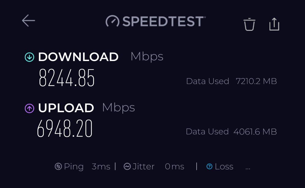
10Gbps networking — is it too fast?
With the emergence of cheap 2.5Gbps solutions, I see them integrated into more and more devices, such as mid-range motherboards, not necessarily top-of-the-range 802.11ax access points and even some laptops. Switching is also fairly inexpensive, an 8-port model with a 10Gb SFP+ uplink can be had for £75. Sure, this is unbranded Chinese stuff, but…
-
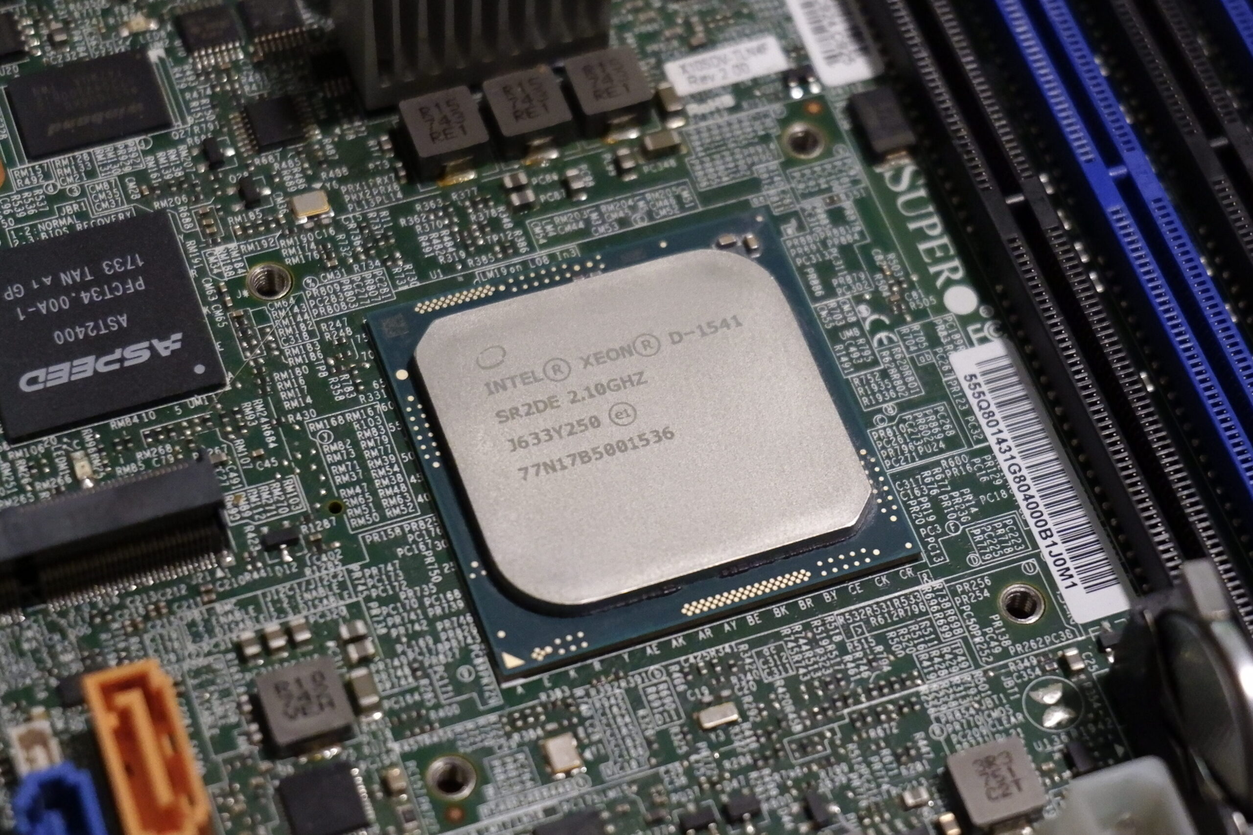
NASv3 on Xeon-D
This article is just a glance at my latest NAS build and isn’t really meant to be a tutorial. I would rather define it as a number of ideas that you can use when they are building their own device. What is a NAS? Network-attached storage (NAS) is a file-level (as opposed to block-level storage) computer data storage server…
-
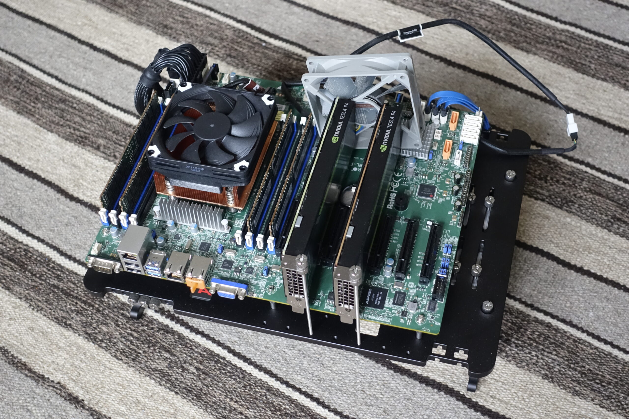
Nvidia vGPUs for gaming
Since I like to play games, and doing so with friends is even better, I decided to put together a hypervisor that could be used to run games on physical LAN parties. It would host a couple of virtual machines with GPU acceleration, all pre-configured to allow incoming RDP connections using Sunshine. Essentially a local…
-

The HP T740
Just like most homelabbers, I like mini PCs. They are cute, use very little power and are quiet, at least in idle and under light loads. The Intel NUCs were at the forefront of this revolution and it’s quite unfortunate that Intel has discontinued that division. The newer generations of Mini PCs seem to have…
-
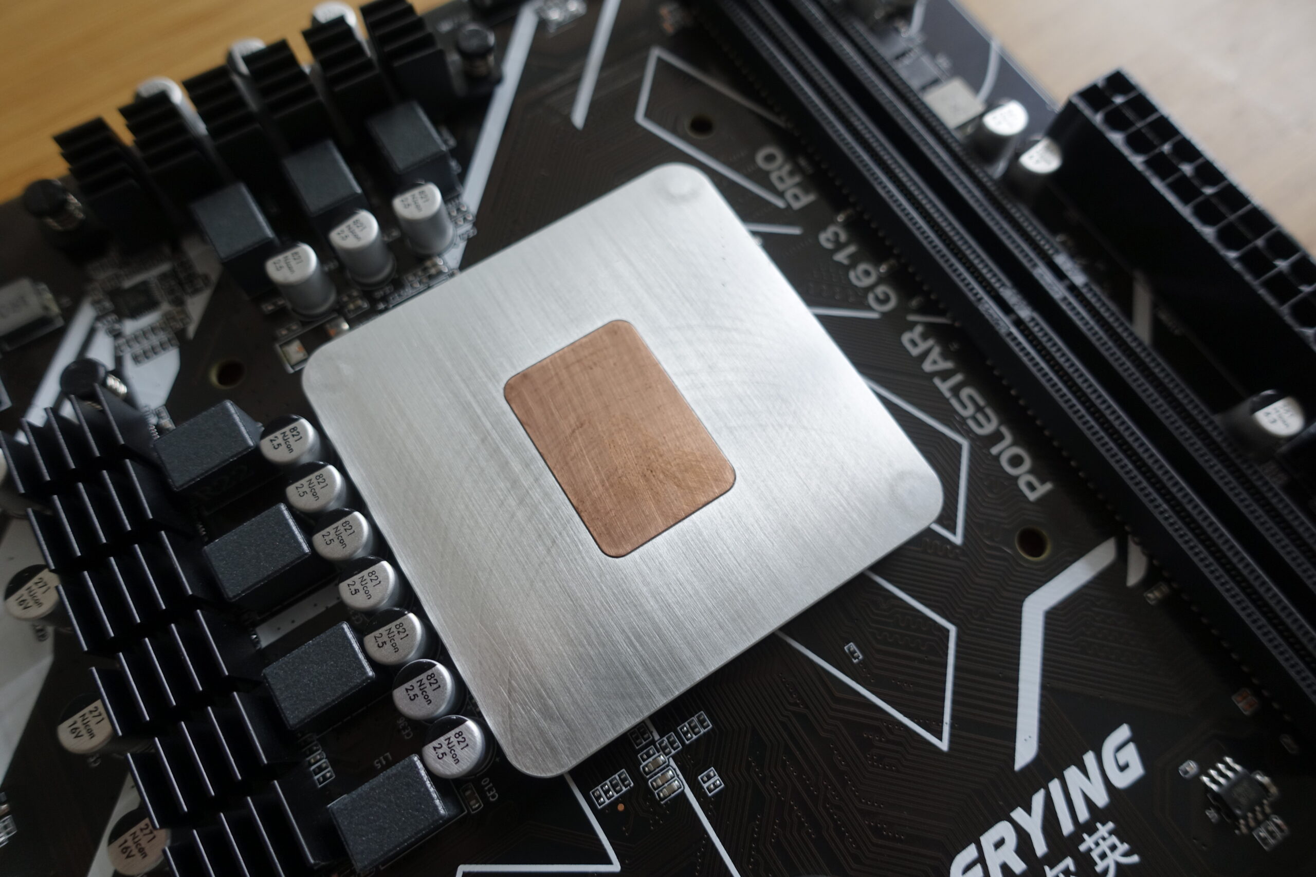
Genuine Intel(R) CPU 0000
For most people, the above probably doesn’t mean much, but those who have a hunch that this article will be about an Engineering Sample are right. I found a cheap Chinese mATX motherboard on Aliexpress which is really interesting for two reasons. One has already been explained by the title, the next will be obvious…
-
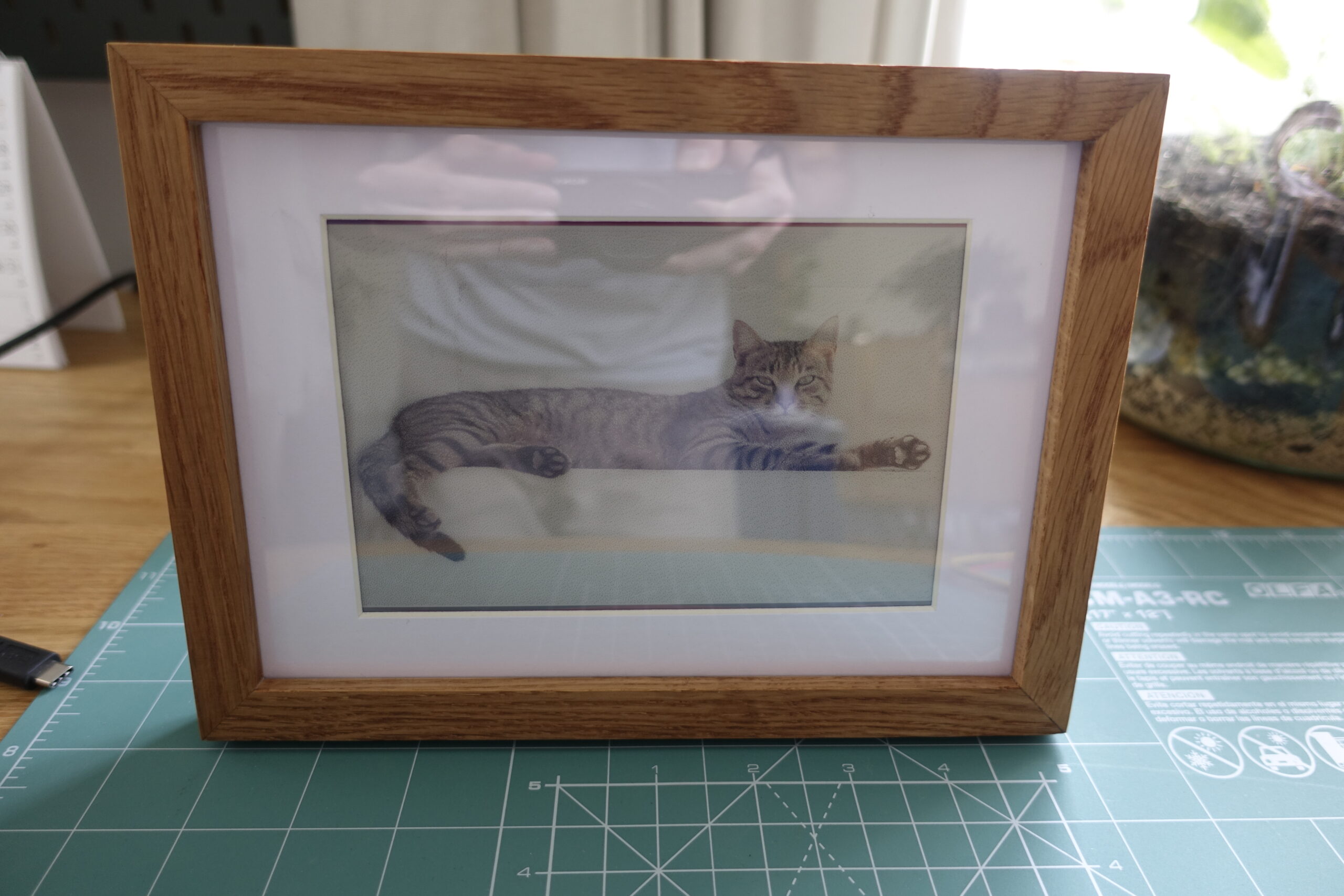
Making a 6×4″ eInk picture frame
My grandmother’s birthday is coming up and I was wondering what to give her when I remembered this video I watched a few months ago on an eink picture frame. I checked pimoroni’s site and they actually had larger, 7″ variants in stock, which can neatly fit in a 10x15cm (6×4″) picture frame, so I…
-
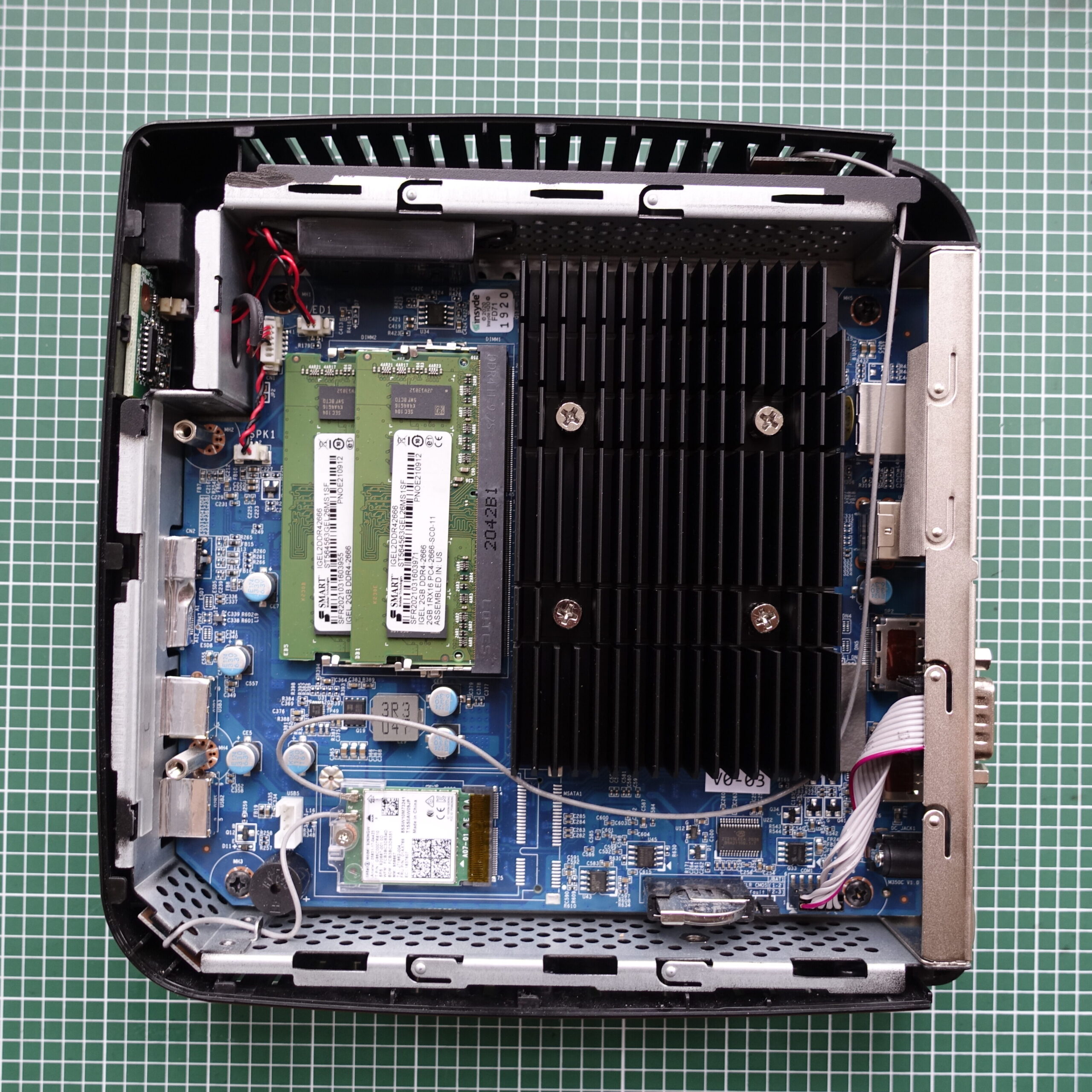
“thin” servers from Thin Clients
The hardware I managed to snatch two Igel M350C thin clients off of ebay for a very reasonable ~$45 per piece, shipped. Which doesn’t sound all that impressive, but these actually have AMD Ryzen Embedded R1505G CPUs. Ryzen Embedded R1505G is a 64-bit dual-core embedded x86 microprocessor introduced by AMD in early 2019. This processor is based on AMD’s Zen microarchitecture and is fabricated on a 14…
-

Deploying WordPress on ORACLE Cloud
This is a guide on how to deploy WordPress (or any other container-based service) on ORACLE Cloud and set up a URL with a Dynamic DNS provider. You could use the guide for a Teamspeak or Minecraft server as well. We’ll use a free-tier ARM-based VM, which utilizes their Ampere Altra 80C CPU. The free-tier…
-
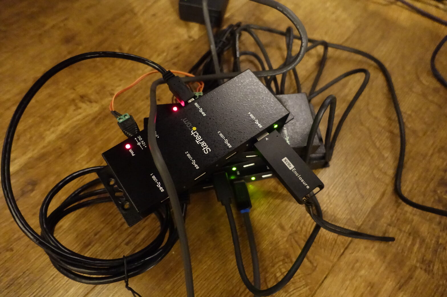
Daisy-chains with USB
Yes, that’s a term that’s usually associated with Thunderbolt or Firewire. It’s also possible with USB4, but that’s not the main focus of this article. I have a few USB hubs on hand and I would like to see if I can chain them up, and if so, how that will affect the performance. I’ve…