which stands for Pico Data Centre. Or, alternatively, NAS 2025v1. Whatever. Naming schemes are fun, but it’s too easy to get carried away with them.
It is intended to be a more portable variant of the MDC, taking most of the hardware from it and repackaging it inside a smaller enclosure.
Why? Because I would like to reduce the number of computers I have and consolidate all the functionality into as few as possible. This will save some space as well as power and might just help me to declutter my living room a bit.
I am also planning to add my thin clients to the picture in a way that would see some of my services distributed across them, so this article may have a few separate parts. One for the hardware, which is going to be this one, and then one (or multiple) for the software setup. I might also try to make my life a bit easier and utilize Terraform or a similar IAC service to make replicating and managing the deployments easier.
I will keep using containers, of course, and aim to set up some sort of load balancing between the hosts, but that’s something I still need to research, as I don’t yet know what the best solution would be to achieve that. I will likely utilize a VPN mesh such as tailscale to connect them to a common network, which would allow me to access them from practically anywhere.
The hardware
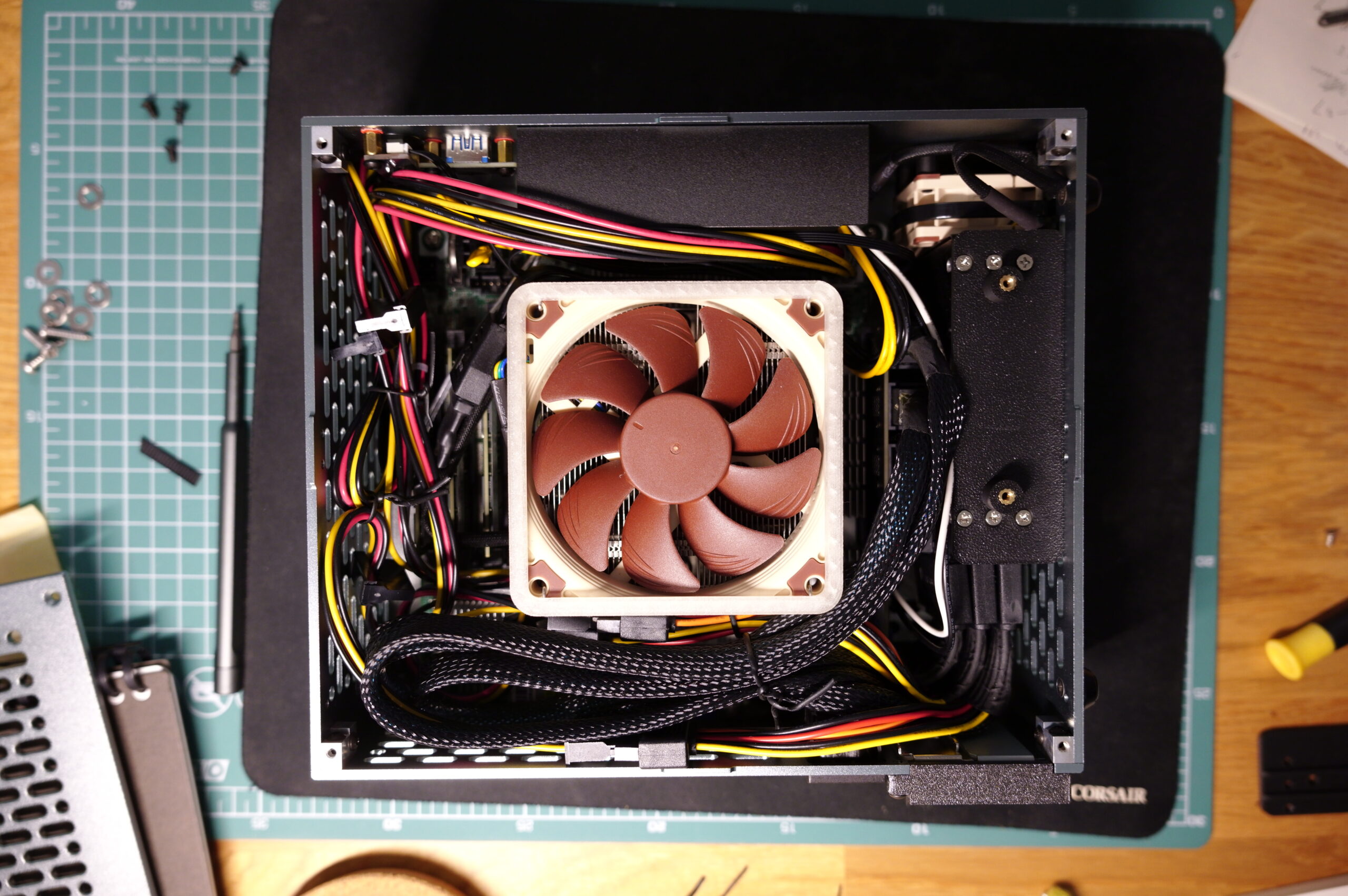
I have taken most of the hardware from the MDC, which includes the AMD 5700G, the ASRock X570D4I-2T and the 128GB of DDR4 memory. What’s new is a Noctua NH-L9x65 cooler, which needs four ~30mm long M3 screws and the Intel bracket to be mounted, as the board has a fixed Intel-style backplate. So, that stays on, the M3 screws go through it from behind and the cooler’s Intel spacers and plates go on the top. It works, but you need to source your own M3 screws.
My 11TB Micron 9200 Eco makes a comeback, it used to be part of an earlier revision of MDC, but since I’ve swapped it out with a number of 3.6TB Huawei SAS drives, it’s just been sitting on a shelf for some time. Now, it isn’t the most power efficient drive, idling at around 10W*, but to complement the 11TB of TLC flash, it has 32 ARM cores and 18GB (bytes, not bits) of DDR4 RAM (16GB + ECC), which make it a very sophisticated piece of engineering and explain its power use.
To compliment it, I will also be adding two Samsung PM963s at 3.84TB each. These are also NVMe drives, but they use much less power and are only 7mm thick. These are essentially m.2 drives in a U.2 package in terms of their power envelopes. I will be running them in RAID 0 to create a mirrored array for stuff I don’t want to lose.
The boot drive will be a 512GB SM961, which I’ve had for ages and, well, it doesn’t need to be anything special, it’s just a boot drive.
*Bonus: U.2 drive power stats
So, I’ve just realized I had a way to measure the power use of the U.2 drives in a slightly more scientific manner, using a U.2 to 10Gbps USB dock, which likely has a JMS582 chipset inside. This is a rather nice setup to assess the idle power consumption, as the dock has a 12V power input, thus I can directly measure the DC power used by the dock. For peak power, this setup is somewhat limited, as the maximum transfer rate of the JMS582 is 10Gbps, so there is no way to fully saturate the speeds of even a PCIe 3.0-based drive. Furthermore, the power used by the JMS582 is also included in the figures, but I don’t think it’s that significant.
| Micron 9200 Eco – 11TB | 7.18W |
| Samsung PM963 – 3.84TB | 2.04W |
| Seagate Nytro 5000 – 1.6TB | 2.88W |
| Micron 7450 Pro – 2TB | 3.96W |
| Huawei HSSD-D5222 – 3.6TB – SAS | 4.56W |
The figures include a few extras, but it is clear that the 9200 Eco is waaay ahead of the rest of the drives. The PM963s are very efficient, but still use a bit more power than traditional SATA drives. They are also not able to fully utilize PCIe 3.0 speeds. They are capped at 2000/1200MB/s R/W speeds. That’s perfectly fine for my use, they will be storing data in a mirrored RAID array and most applications will reside on and use the Micron 9200.
The enclosure
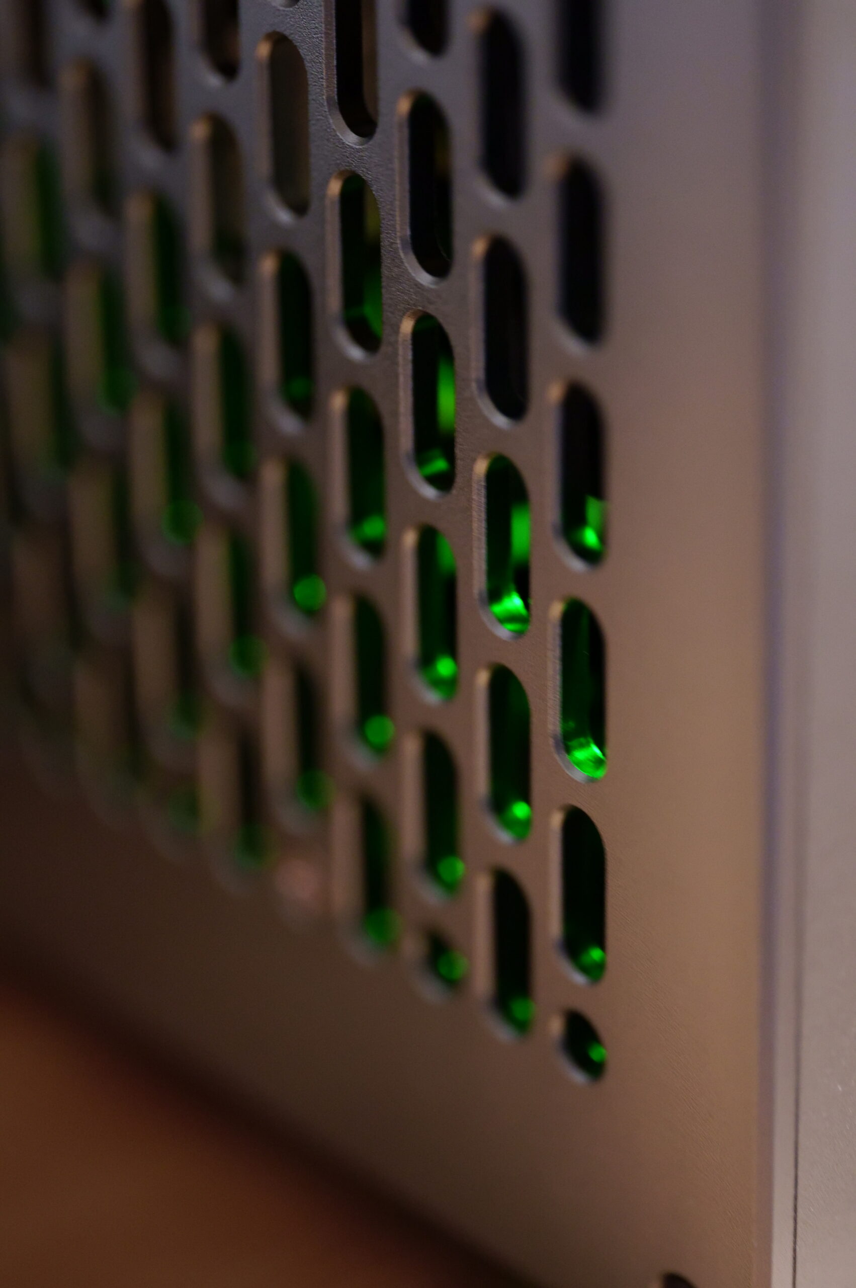
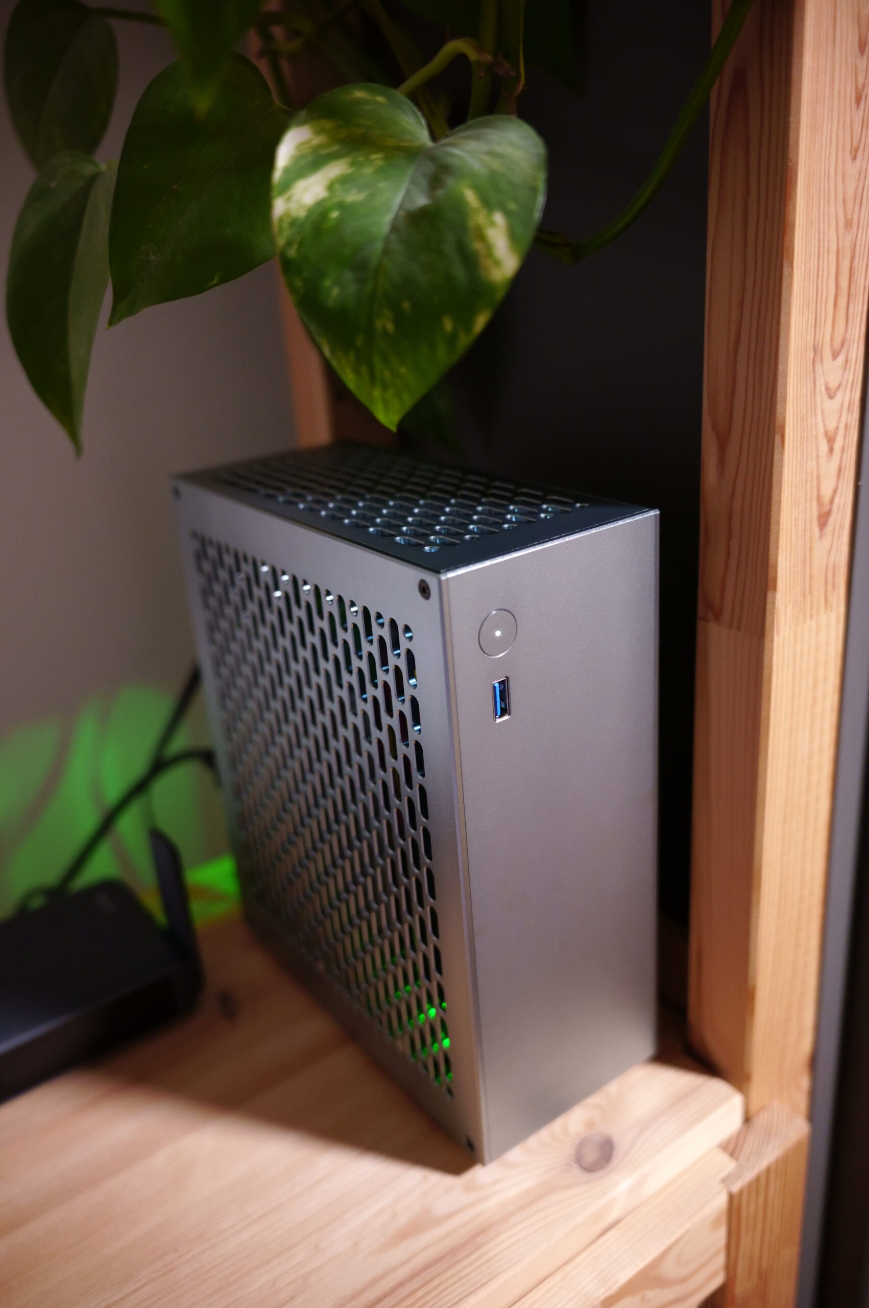
Of course, the most important part of an SFF build is the case. For this, I used an LLW’s Workshop V40 ITX case from Taobao. It has almost reached the status of unobtanium, it’s impossible to get it on aliexpress as all the orders I placed got cancelled due to the selers being unable to fulfill them, so I would like to take the opportunity to thank Wei for getting it for me. The panels are nicely machined and they have a highly reflective finish. The colour is supposed to be space gray (太空灰色) which essentialy means a darker silver with a very slight touch of purple.

This is a very small 4 liter case that is meant to be used with a 300W Mean Well 12V-only power supply. Normally, that would go to a Pico PSU, but since my board can run on 12V only, I could connect the PSU straight to the 8-pin EPS power input and call it a day. There are some other server boards like this from ASRock Rack, as well as Gigabyte and Supermicro. The PSU is also thermally coupled to the front aluminium piece of the case with some thermal pads, which I thought was an especially nice touch. I custom made the cable between the PSU and the motherboard and I’ve also added a 12V output connector to the back of the case if I ever needed 12V for, let’s say, a dock or enclosure.
The case was originally meant for a gaming-orineted config with a low-profile RTX4060 and had no mounting holes for 2.5″ drives. That needed to be changed, so I 3D-printed two brackets to hold the two 7mm PM963s and the 15mm Micron 9200. I added some threaded inserts that can be melted into the plastic and screwed this to the side panels on both sides using M3 screws, so it stays in place securely, even if the case is handled without care. The drives also got a 40mm fan blowing air at them from the front, and there are 2mm gaps left between them to allow that air to pass. There is just enough space between the MB and the bottom panel of the case for them to fit.

The fan is just ziptied in place with some 3D-printed spacers in front to ensure it doesn’t slide around. You might just be able to see them in the upper right corner of the photo above.
I’ve added a 4mm thick air baffle to the CPU fan, which ensures that it pulls in all of the air from the outside instead of circulating it inside the case. This was printed using transparent plastic, which makes it somewhat visible in the dark. I’ve thought of illuminating it with some LEDs, but I just haven’t got the time for that at the moment.
Thermals
This is a server board.
There is an Intel X550 NIC onboard, as well as the infamous and toasty AMD X570 chipset.
And the only fan that has any chance of moving some air around them is the CPU fan. So I need to run it at least at around 1300rpm to ensure that everything gets sufficient cooling, even if the CPU itself doesn’t really need it. This way, the chipset stays around 65℃, which is not the best, but it is workable. All drives are connected directly to the PCIe lanes of the CPU, using the PCIe slot, to minimize the amount of data flowing through the chipset. I don’t have any data to show that this would in any way reduce the power consumption of the chipset, but I imagine it should help in some way, however negligible that may be. The X550 is actually very much okay, I’ve only ever used one of its ports at a time and never had an overheating issue. Yes, it is hot to the touch, but that doesn’t seem to cause any issues.
I also like to limit the turbo speeds and voltages of the 5700G by manually adjusting the maximum P states. I think I currently have it set to 4.3Ghz and 1.16V, which corresponds to a hex value of 3E. This helps to reduce the peak power while retaining most of the performance and makes the CPU run much more efficiently. The values that work with your CPU may vary. I believe I also tried 3.5Ghz with 1.0V, which has a hex value of 58 and that also worked quite well, but I didn’t spend a lot of time tweaking it, so it is possible that the frequencies could be increased and/or the voltage could be decreased further. Only try it at your own risk. It won’t damage your board or CPU, but it may make them unstable and cause crashes and/or data loss.
Final words
So, was it worth it overall?
Well, I have managed to rebuild what used to be the MDC in less than half of its original volume, while retaining all of its performance and giving me more storage than I know what to do with.
It is very quiet, can easily live in a living room without disturbing those around it and is quite power efficient, at least given the fact that it has 19TB of fast solid state storage and integrated 10GbE.
I was really eyeing some of the newer 13th-gen Erying boards that have mobile CPUs and USB4, but I already had the hardware and didn’t want to replace everything. Plus, it is nice to have an integrated IPMI and a second integrated GPU that can potentially be used for GPU passthrough. (The primary being the IPMI’s VGA output, which is what’s used at boot. The 5700G’s integrated GPU is active, but has no display outputs, so it can only help with acceleration.)

Leave a Reply